
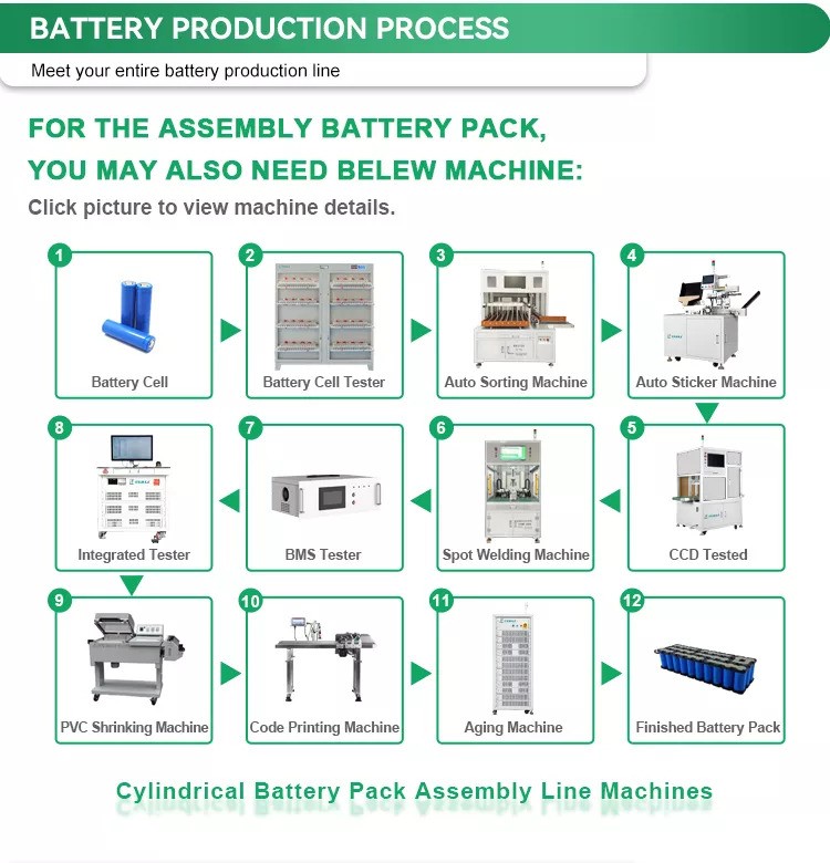
Battery packs power everything from electric vehicles to smartphones. But have you ever wondered how they’re made? The battery pack manufacturing process is a complex, multi-step procedure ensuring efficiency, safety, and longevity.
Understanding how battery packs are manufactured is crucial as industries demand higher performance and sustainability. From raw material selection to final assembly, each step plays a vital role in quality and reliability.
In this post, you’ll learn the entire battery pack manufacturing process. We’ll cover cell selection, module assembly, safety testing, and future innovations. Whether you’re a professional or a curious reader, this guide will provide a clear and detailed overview.
Battery Cell Selection and Procurement
The foundation of any high-performance battery pack begins with selecting the right battery cells. This critical decision influences the overall performance, lifespan, safety, and cost of the final battery pack.
Types of Battery Cells Used in Battery Packs
Different applications require specific types of battery cells based on their unique characteristics:
| Battery Cell Type | Energy Density | Cycle Life | Cost | Typical Applications |
|---|---|---|---|---|
| Lithium-ion | High | 500-1000+ | High | Portable electronics, EVs |
| Lead-acid | Low | 200-300 | Low | UPS, emergency lighting |
| Sodium-ion | Medium | 500+ | Medium | Grid storage, renewable energy |
| Nickel-metal hydride | Medium | 300-500 | Medium | Power tools, medical devices |
Factors to Consider When Selecting Battery Cells
When choosing battery cells for a specific application, manufacturers must evaluate:
- Voltage requirements – Individual cell voltage must align with the desired pack voltage
- Capacity needs – Energy storage requirements determine cell capacity selection
- Cycle life expectations – Applications requiring longevity need cells with superior cycle life
- Internal resistance – Lower resistance cells provide better performance and less heat generation
- Temperature operating range – Cells must function reliably in the intended environment
- Safety profile – Thermal stability and overcharge protection capabilities
Raw Materials Used in Battery Cells
The performance of battery cells depends significantly on their raw material composition:
- Lithium – Active material enabling energy storage and release
- Cobalt and Nickel – Cathode materials enhancing energy density
- Graphite – Anode material maintaining electrolyte stability
- Aluminum and Copper – Current collectors for cathode and anode respectively
- Electrolyte compounds – Facilitating ion movement between electrodes
Procurement Process for Raw Materials and Battery Cells
A systematic procurement approach ensures quality and consistency:
- Requirements specification – Defining technical needs and performance parameters
- Supplier qualification – Evaluating potential suppliers based on quality, reliability, and capacity
- Quality testing – Verifying cells meet specifications for voltage, capacity, and internal resistance
- Batch consistency verification – Ensuring voltage difference between cells is minimal (typically <5mV)
- Supply chain management – Establishing reliable sources for raw materials and finished cells
Effective cell selection and procurement lay the groundwork for successful battery pack manufacturing, directly impacting the quality and performance of the final product.
Battery Cell Manufacturing Process
The battery cell manufacturing process is a complex, multi-step procedure that ensures the efficiency, safety, and longevity of battery packs. It consists of three major stages: electrode manufacturing, cell assembly, and cell finishing. Each step plays a crucial role in determining the battery’s performance and reliability.
1. Electrode Manufacturing
Electrode manufacturing is the foundation of battery cell production. This stage involves preparing the anode and cathode materials and ensuring uniformity for optimal battery performance.
1.1 Mixing Anode and Cathode Materials
- Cathode Composition: A mix of active material (e.g., NMC622), polymer binder (e.g., PVdF), solvent (e.g., NMP), and conductive additives (e.g., carbon).
- Anode Composition: Typically contains graphite, carbon black, and a polymer binder (e.g., carboxymethyl cellulose – CMC).
- Challenges: Ensuring a homogeneous slurry mix, controlling water content, and avoiding contamination from metal particles.
1.2 Coating Process for Electrodes
- The electrode slurry is applied onto a metal foil (cathode on aluminum, anode on copper).
- Challenges: Controlling coating thickness, avoiding edge build-ups, and maintaining uniformity across the foil.
1.3 Drying and Calendering of Electrodes
- Drying: Removes residual solvents using convective air dryers.
- Calendering: Rolls electrodes to achieve desired thickness and porosity.
- Challenges: Preventing cracking, ensuring uniform pressure, and optimizing surface smoothness.
2. Cell Assembly
This stage involves cutting, stacking, or winding electrodes with separators before enclosing them in casings.
2.1 Slitting and Cutting Electrodes
- Electrodes are trimmed to the exact dimensions required for assembly.
- Challenges: Avoiding burrs, preventing short circuits, and ensuring clean edges.
2.2 Stacking or Winding Electrodes with Separators
- For Cylindrical Cells: The electrodes and separator are wound into a spiral (“jelly roll”).
- For Prismatic/Pouch Cells: The electrodes are stacked in layers with separators.
- Challenges: Ensuring proper alignment, preventing punctures, and minimizing separator defects.
2.3 Inserting into Cell Casing
- The stacked/wound electrodes are placed into cylindrical, prismatic, or pouch casings.
- Challenges: Preventing contamination, maintaining air-tight seals, and securing electrode alignment.
3. Cell Finishing
The final stage includes electrolyte filling, formation, aging, and quality control testing.
3.1 Electrolyte Filling and Sealing
- The cell is filled with a precise volume of electrolyte solution under a vacuum to ensure complete wetting.
- The casing is temporarily sealed to allow for gas venting.
- Challenges: Maintaining low water content, ensuring complete wetting, and avoiding contamination.
3.2 Formation and Aging Process
- Formation: The cell is slowly charged and discharged to build a solid-electrolyte interface (SEI).
- Degassing: Gases formed during initial charging are removed before final sealing.
- Aging: Cells are stored under controlled temperatures to stabilize chemical reactions.
- Challenges: Preventing overcharging, controlling temperature fluctuations, and reducing production time.
3.3 Final Control Checks and Testing
- Open-Circuit Voltage (OCV) Testing: Ensures cells meet voltage standards.
- Leakage Testing: Confirms airtight seals.
- Capacity Testing: Verifies energy storage capacity.
- Thermal Safety Checks: Ensures cells withstand temperature variations.
Battery Module Assembly
The battery module assembly process is a crucial step in the battery pack manufacturing process, where individual battery cells are grouped into modules. This stage enhances efficiency, safety, and performance by integrating electrical connections, thermal management systems, and safety features.
Grouping Cells into Modules
Battery cells are arranged and connected in a structured manner to form modules. Proper configuration ensures optimized voltage, capacity, and reliability.
Series and Parallel Connections
- Series Connection (S): Increases voltage by connecting cells end-to-end.
- Parallel Connection (P): Increases capacity by connecting cells side-by-side.
- Hybrid Configurations: Combine both series and parallel connections to achieve desired power output.
| Configuration | Effect | Example |
|---|---|---|
| 4S1P | Voltage x4, same capacity | 14.8V, 2Ah |
| 1S4P | Same voltage, capacity x4 | 3.7V, 8Ah |
| 3S2P | Voltage x3, capacity x2 | 11.1V, 4Ah |
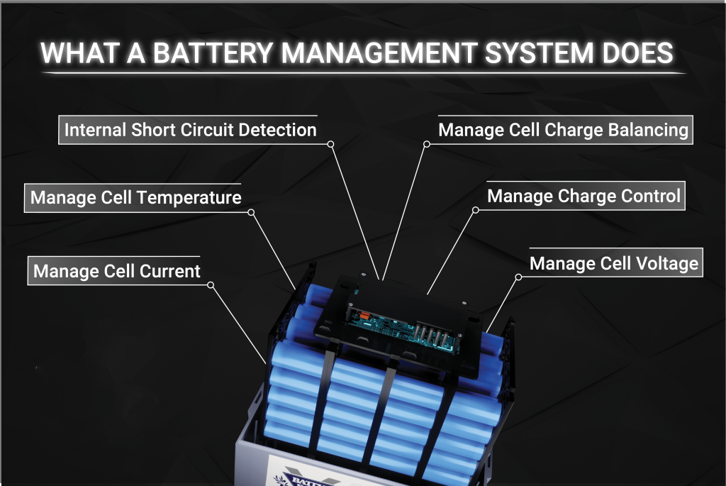
Balancing and Monitoring with a Battery Management System (BMS)
- The BMS ensures uniform charge and discharge among all cells.
- Active Balancing: Redistributes charge between cells to maximize lifespan.
- Passive Balancing: Uses resistors to discharge excess energy from fully charged cells.
- The BMS prevents overcharging, overheating, and deep discharge, ensuring safety and efficiency.
Key Quality Standard: The voltage difference between battery cells should be less than 5mV, and internal resistance difference less than 2mΩ to ensure balanced operation.
More information about BMS test.
Adding Thermal Management Components
Battery modules generate heat during charge and discharge cycles. Proper thermal management prevents overheating, degradation, and thermal runaway.
Heat Sinks and Thermal Pads
- Heat sinks dissipate heat from high-power modules.
- Thermal pads fill gaps between cells and enclosures, enhancing heat transfer.
Cooling Systems (Air, Liquid, or Passive)
| Cooling Method | Description | Common Applications |
|---|---|---|
| Air Cooling | Uses fans or natural convection. Low cost but less efficient. | Consumer electronics, small EVs |
| Liquid Cooling | Circulates coolant through pipes for superior heat dissipation. | High-performance EVs, industrial storage |
| Passive Cooling | Uses phase-change materials or thermal buffers. No moving parts. | Energy storage, low-power devices |
Integrating Safety Features
Multiple protection mechanisms safeguard against potential failures:
- Overcurrent Protection: Fuses and circuit breakers prevent excessive current flow
- Voltage Management: Protection circuits monitor and maintain safe voltage levels
- Short-Circuit Prevention: Insulation materials and physical barriers between conductive elements
- Cell Balancing Circuits: Prevent individual cells from overcharging or discharging excessively
- Thermal Runaway Prevention: Temperature sensors trigger protective measures when detecting abnormal heat
Each module undergoes rigorous testing after assembly, including communication tests, function verification, and quality inspections before advancement to the final pack assembly stage.
Battery Pack Assembly
The final stage of battery manufacturing involves combining individual modules into a cohesive power unit that delivers the specified voltage, capacity, and performance characteristics. This critical phase transforms modular components into a complete battery pack ready for installation in its intended application.
Connecting Modules to Form a Complete Battery Pack
The assembly process follows a systematic approach to ensure optimal performance:
- Module Arrangement: Positioning modules according to design specifications
- Electrical Connections: Establishing robust connections between modules
- Busbar Installation: Installing conductive bars to facilitate current flow
- Insulation Application: Adding protective barriers between conductive elements
Installing the Pack into a Protective Housing
The protective enclosure serves multiple functions beyond basic protection:
- Structural Support: Maintains proper alignment of internal components
- Environmental Protection: Shields against moisture, dust, and physical damage
- Mounting Interface: Provides attachment points for installation
- Thermal Management: Facilitates heat dissipation and temperature regulation
Assembly Technique: Many manufacturers utilize ultrasonic welding technology to seal plastic enclosures, ensuring long-term durability without compromising structural integrity.
Wiring the Modules and BMS
An integrated approach to electrical connectivity ensures reliable operation:
| Component | Function | Implementation Considerations |
|---|---|---|
| Power Connections | Carry main current | Heavy gauge wiring with minimal resistance |
| Sensing Wires | Monitor cell/module voltage | Shielded cables to prevent interference |
| Communication Lines | Exchange data with control systems | Protected from electromagnetic interference |
| BMS Integration | Monitor and protect the system | Strategically positioned for optimal function |
Implementing Advanced Thermal Management Systems
Temperature control systems are selected based on application requirements:
- Air Cooling: Fans circulate air through channels for moderate cooling needs
- Liquid Cooling: Fluid passes through plates or tubes for high-power applications
- Heat Pipes: Passive systems transfer heat away from sensitive components
- Phase Change Materials: Absorb excess heat during peak operation periods
Incorporating Additional Safety Mechanisms
Safety is paramount in battery pack design. Several protective measures are integrated:
- Fuses: Prevent overcurrent damage.
- Overvoltage Protection: Stops overcharging hazards.
- Short-Circuit Prevention:
- Insulated connectors.
- Fault detection circuits.
- Automatic shutdown mechanisms.
✅ Key Safety Standards:
- UN 38.3 (Lithium battery transport safety)
- IEC 62133 (Battery safety for consumer applications)
- ISO 26262 (Automotive functional safety)
Testing and Quality Control in Battery Pack Manufacturing
Ensuring the reliability, efficiency, and safety of battery packs requires rigorous testing and quality control measures. The battery pack manufacturing process includes multiple tests to verify performance, durability, and compliance with industry standards. Below are the critical testing stages.
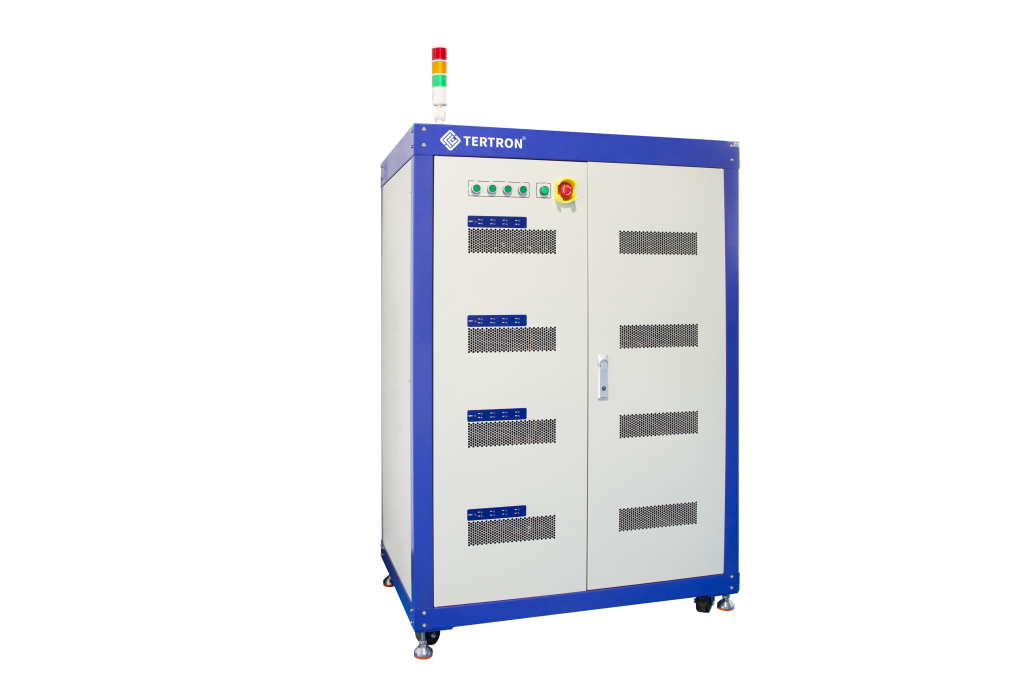
1.Charge/Discharge Cycling Tests
Charge and discharge cycles are performed to simulate real-world usage and measure the battery pack’s lifespan.
- Purpose: Ensures the pack can handle repeated charging and discharging without significant degradation.
- Process:
- The battery is charged to full capacity.
- It is then discharged under controlled conditions.
- This cycle is repeated hundreds or thousands of times to measure aging.
- Key Metrics:
- Cycle life (number of cycles before capacity drops below 80%).
- Energy efficiency (charge vs. discharge ratio).
- Self-discharge rate.
✅ Result: Ensures the battery can sustain long-term use in electric vehicles, energy storage, and portable devices.
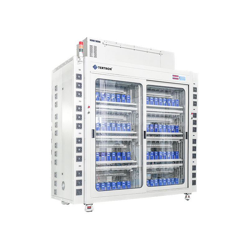
2. Battery Management System (BMS) Functionality Tests
The Battery Management System (BMS) plays a crucial role in monitoring, balancing, and protecting the battery pack.
- Tests Performed:
- Open-Circuit Voltage (OCV) Test: Measures voltage stability.
- Balancing Test: Checks if the BMS distributes charge evenly across cells.
- Overvoltage/Undervoltage Protection: Ensures cut-off activation at dangerous voltage levels.
- Current Regulation Test: Prevents excessive current flow.
| BMS Function | Purpose | Test Outcome |
|---|---|---|
| Voltage Regulation | Ensures balanced charging and discharging | Stable power output |
| Overcharge Protection | Prevents damage from excessive charging | Safe voltage limits |
| Undervoltage Protection | Avoids deep discharge that degrades cells | Enhanced lifespan |
| Temperature Monitoring | Prevents overheating and thermal runaway | Controlled operation |
✅ Result: Guarantees battery stability, safety, and efficiency in real-world applications.
3. Safety Tests (Thermal, Electrical, Overcharge/Discharge Protection)
Battery packs must withstand thermal, electrical, and mechanical stresses without failure.
3.1 Thermal Testing
- Simulates extreme temperatures to check battery performance under hot and cold conditions.
- Thermal runaway detection to prevent fire hazards.
3.2 Electrical Safety Tests
- Short-circuit simulation: Ensures automatic shutdown mechanisms activate correctly.
- Overcurrent protection test: Prevents battery damage from sudden surges.
- Dielectric strength test: Verifies insulation strength against electrical breakdown.
3.3 Overcharge and Overdischarge Protection
- The battery is forced into overcharge/discharge scenarios to verify BMS cut-off functionality.
- Prevents explosion risks and chemical instability.
✅ Result: Ensures the battery does not overheat, short-circuit, or become unstable under stress.
4. Capacity and Performance Verification
Battery packs are tested to ensure they meet energy storage and output expectations.
- Capacity Test:
- Measures actual energy storage (Ah or Wh).
- Compares with rated capacity to verify accuracy.
- Performance Test:
- Assesses voltage, current, and power efficiency.
- Measures internal resistance affecting battery longevity.
- Tests under varied loads (high/low power draws).
| Test Type | Purpose | Key Metric |
|---|---|---|
| Capacity Test | Ensures battery holds expected charge | Measured in Ah/Wh |
| Load Performance | Measures efficiency under different loads | Voltage & current stability |
| Internal Resistance | Checks energy loss inside battery | Lower resistance = better efficiency |
✅ Result: Confirms battery meets operational requirements for its intended application.
5. Compliance with Industry Standards and Regulations
Battery packs must meet international safety and performance standards to be legally used in EVs, energy storage, medical devices, and consumer electronics.
Key Industry Certifications
| Standard | Regulatory Body | Scope |
|---|---|---|
| UN 38.3 | United Nations | Transport safety for lithium batteries |
| IEC 62133 | IEC | Battery safety for consumer devices |
| ISO 26262 | ISO | Functional safety in automotive applications |
| UL 1642 | Underwriters Laboratories | Lithium-ion battery safety |
| RoHS | EU | Restriction of hazardous materials |
- Compliance Testing Includes:
- Environmental impact assessments.
- Recycling and disposal safety.
- Mechanical stress resistance.
✅ Result: Ensures the battery meets safety regulations for global markets.
Customization and Specific Applications in Battery Pack Manufacturing
Battery packs are not one-size-fits-all solutions. Different industries require customized battery packs tailored to specific voltage, capacity, and form factor requirements. Customization ensures optimal performance, safety, and efficiency for various applications, including electric vehicles (EVs), consumer electronics, and energy storage systems.
1. Customizing Battery Packs for Specific Requirements
Manufacturers customize battery packs based on technical and physical specifications to meet application needs.
1.1 Key Customization Parameters
| Customization Factor | Description |
|---|---|
| Voltage (V) | Determines power output; configured via series connections. |
| Capacity (Ah/Wh) | Affects runtime and energy storage; adjusted through parallel configurations. |
| Size & Shape | Designed to fit specific enclosures or compact spaces. |
| Weight | Optimized for portability or heavy-duty applications. |
1.2 Customization Process
- Assessing Client Requirements: Identifying power needs, form factor, and environmental conditions.
- Design & Prototyping: Creating CAD models and prototypes to optimize performance.
- Battery Chemistry Selection: Choosing between Li-ion, LiFePO4, NiMH, or custom chemistries.
- Integration with BMS: Ensuring real-time monitoring, protection, and optimization.
- Testing & Validation: Conducting capacity, thermal, and cycle life tests.
2. Battery Packs for Different Applications
Each industry has unique energy requirements. Below are some common battery applications and their specialized pack designs.
2.1 Electric Vehicles (EVs)
- High-voltage battery packs (200V–800V) for extended range.
- Fast-charging capabilities to minimize downtime.
- Thermal management systems to prevent overheating.
2.2 Consumer Electronics
- Compact and lightweight designs for smartphones, laptops, and wearables.
- Energy-dense lithium-ion cells for long battery life.
- Fast discharge rates for high-performance gadgets.
2.3 Energy Storage Systems (ESS)
- High-capacity packs (kWh to MWh range) for renewable energy storage.
- Modular battery systems for scalable applications.
- Enhanced cycle life (5000+ cycles) for long-term reliability.
| Application | Voltage Range | Capacity | Key Features |
|---|---|---|---|
| EV Batteries | 200V–800V | 40–100 kWh | Fast-charging, thermal cooling |
| Laptops/Smartphones | 3.7V–11.1V | 2–10Ah | Lightweight, high energy density |
| Solar Storage | 48V–400V | 10 kWh–1 MWh | Scalable, long cycle life |
3. Importance of Close Collaboration Between Manufacturers and Clients
Custom battery packs require seamless collaboration between manufacturers and clients to ensure tailored solutions.
3.1 Benefits of Manufacturer-Client Collaboration
- Optimized Design: Ensures the best power-to-weight ratio and size compatibility.
- Industry-Specific Adaptations: Allows for application-specific features like waterproofing or ruggedized enclosures.
- Regulatory Compliance: Guarantees that battery packs meet safety and certification standards (UN 38.3, IEC 62133).
3.2 Steps for Effective Collaboration
- Requirement Analysis – Understanding energy, voltage, and cycle life needs.
- Material Selection – Choosing the right battery chemistry and protective casing.
- Prototype Development – Testing and refining battery packs before mass production.
- Final Production & Quality Testing – Ensuring durability, reliability, and compliance.
Packaging, Shipping, and Installation
The final stages of the battery pack manufacturing process involve careful handling, transportation, and implementation to ensure products reach their destination safely and function as intended.
Protective Packaging for Transportation
Battery packs require specialized packaging to prevent damage:
- Foam Cushioning: Absorbs shocks and vibrations during transit
- Rigid Outer Containers: Provides structural protection
- Wooden Racks: Offers additional support for larger battery systems
- Anti-static Materials: Prevents electrical discharge damage
Documentation and Warranty Inclusion
Each shipment contains essential information:
Complete Documentation Package: Performance test results, warranty information, user manuals, and installation guidelines accompany each battery pack, ensuring proper implementation and operation.
Hazardous Materials Shipping Considerations
| Requirement | Purpose | Implementation |
|---|---|---|
| UN Certification | Verifies packaging meets international standards | Testing and labeling |
| Hazard Labels | Identifies battery contents for handlers | Standardized markings |
| Shipping Declarations | Documents battery specifications | Detailed manifests |
| Transport Regulations | Ensures compliance with carrier requirements | Mode-specific protocols |
Installation and Commissioning
The installation process follows systematic steps:
- Site Preparation: Ensuring appropriate environment and mounting infrastructure
- Unpacking Procedures: Careful removal from protective packaging
- Placement and Securing: Mounting according to specifications
- Initial Testing: Verifying functionality before integration
- Commissioning: Calibrating the system for optimal performance
System Integration
Battery packs connect to broader systems through specialized interfaces, including inverters for DC-to-AC conversion in solar applications, control systems for industrial implementation, and monitoring platforms for performance tracking throughout operational life.
Maintenance and Monitoring
After installation, battery packs require consistent attention to maintain optimal performance and longevity. Implementing regular maintenance protocols and continuous monitoring systems ensures reliable operation throughout the battery pack’s service life.
Regular Maintenance Tasks
A structured maintenance schedule helps prevent potential issues:
- BMS Functionality Verification
- Check for firmware updates
- Verify communication protocols
- Confirm accurate voltage readings
- Test protection functions
- Cell Health Assessment
- Monitor internal resistance trends
- Evaluate capacity retention
- Check for voltage imbalances
- Inspect for physical changes
- Thermal Management Inspection
- Clean cooling components
- Verify fan operation
- Inspect thermal interfaces
- Check temperature sensors
Importance of Ongoing Monitoring
Continuous monitoring provides critical insights into battery performance trends, allowing operators to identify potential issues before they lead to system failures or reduced efficiency.
Effective monitoring systems track key parameters:
| Parameter | Monitoring Frequency | Action Threshold |
|---|---|---|
| Cell Voltage | Continuous | ±5% variation |
| Temperature | Continuous | Outside 10-40°C range |
| Internal Resistance | Monthly | >20% increase |
| Capacity | Quarterly | <80% of rated capacity |
Replacing or Upgrading Components
Components may require replacement based on:
- Performance Degradation: When efficiency falls below acceptable levels
- End-of-Life Indicators: Components reaching design lifetime
- Technology Advancements: When newer solutions offer significant improvements
- System Expansion: When additional capacity or capabilities are needed
Periodic charging/discharging cycles at recommended intervals help maintain optimal chemical balance within cells, extending overall system lifespan and ensuring consistent performance.
Future Trends and Developments
The battery pack manufacturing industry continues to evolve rapidly, with emerging technologies and processes poised to transform production capabilities, performance metrics, and environmental impact in the coming years.
Advancements in Battery Cell Chemistry and Technology
Next-generation battery technologies promise significant improvements:
- Solid-state electrolytes replacing liquid components for enhanced safety
- Silicon-enriched anodes increasing energy density by up to 40%
- Lithium-sulfur chemistry potentially tripling energy capacity
- Sodium-ion alternatives reducing dependency on rare materials
Improvements in Manufacturing Processes and Automation
Manufacturing innovations are revolutionizing production efficiency:
Industry 4.0 integration enables real-time monitoring and adaptive process control throughout battery pack assembly, significantly reducing defect rates while improving traceability.
Increasing Focus on Sustainability and Recycling
| Sustainable Development | Current Status | Future Direction |
|---|---|---|
| Material Recovery | 50-60% recovery rate | 95%+ closed-loop systems |
| Carbon Footprint | Energy-intensive production | Renewable-powered facilities |
| Design Approach | Difficult disassembly | Design-for-recycling standards |
| Second-life Applications | Limited implementation | Standardized repurposing pathways |
Potential Impact of New Technologies
Emerging technologies will transform battery pack manufacturing:
- AI-driven quality control detecting microscopic defects invisible to conventional systems
- Digital twin technology simulating battery performance before physical production
- Additive manufacturing enabling custom cell designs and reduced material waste
- Self-healing materials extending battery life through automatic damage repair
These developments collectively point toward battery packs with higher energy density, longer lifespan, faster manufacturing times, and substantially improved environmental credentials.
Conclusion
The battery pack manufacturing process involves cell selection, module assembly, wiring, thermal management, and safety integration. Each step ensures efficiency, reliability, and durability.
Understanding this process helps manufacturers optimize production, clients get tailored solutions, and consumers receive safer, longer-lasting batteries.
As technology advances, improvements in materials, energy density, and sustainability will shape the future of battery innovation. Efficient manufacturing will drive better performance, safety, and eco-friendly solutions.
Have questions about the battery pack manufacturing process? Contact Tertron for expert guidance. Get clear answers on cell selection, assembly, testing, and safety. Ensure your battery packs meet performance and industry standards. Reach out today for reliable solutions.